
Vector Array™ Gen2
High-density silicon for deep brain structures in large animals
Deep Brain Recording and Microstimulation
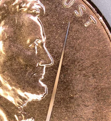
A silicon electrode array at the working end of a rigid stainless-steel support body. The array reaches subcortical targets in primates and other large animals, and records and stimulates where a silicon shank alone would flex or break on the way down.
A Short Array on a Long Support Body
The support body resists buckling over the full trajectory; the rest of the shank is structure, not electrode. Three consequences follow, and all three belong in the surgical plan.
The recording span is short relative to the tract
You are sampling one window at the end of the trajectory, not profiling the trajectory. Position the array on the structure and accept that everything above it is unrecorded.
The support body sets the tract diameter
315 µm OD at 16 channels, 400 µm at 32 and 64, 635 µm at 128 — wider than a silicon shank. Plan the approach along its whole length, not only at the tip.
Angular error scales with depth
An error invisible at 2 mm places the array outside a small nucleus at 15 mm. Use imaging where the model allows it, and confirm the track histologically afterwards.
What Gen2 Adds
Reinforced Design
Added structural reinforcement against breakage, for improved longevity over repeated use.
Fusion-Style Double-Sided Recording
Sites on both faces — roughly twice the active sites in nearly the same footprint, so spatial coverage rises without the shank displacing more tissue.
Expanded Channel Count
Record and stimulate from up to 128 channels, acute or chronic, on the same electrode geometry and contact density as the rest of the range.
Five Builds, Two Independent Choices
| Build | Silicon thickness | What it gives you |
|---|---|---|
| Standard | 50 µm | The default array. |
| Fusion-style double-sided | 100 µm | Sites on both faces — roughly twice the active sites in nearly the same footprint. This is the 128-channel build, carried on the FV128 package. |
| Reinforced | 150 or 200 µm | Structural reinforcement against breakage, and improved longevity. |
| Chronic | — | Configures to an implantable 30 to 55 mm, for targets past 10 mm. Factor in implantation hardware such as clamps. |
| Opto | — | Mounts a flat optical fiber alongside the array, on the same trajectory as the electrodes. |
Specifications
The standard Gen2 build. The catalog also carries three designs at 15 mm, one at 12 mm, and two tetrode designs at 121 µm² sites.
Reach
Total length 70 mm or 110 mm; implantable lengths up to 110 mm. Silicon electrode length 10 mm.
Channels and sites
16, 32, 64 or 128 channels. Site area 177 µm²; site coverage 375 µm to 6,300 µm depending on design.
Shank
Silicon electrode width 20 µm minimum on the edge design, 75 µm minimum on Poly2, 175 µm maximum. Iridium sites, with SIROF available.
Reusability
With proper care a single array is reusable across 50 or more experiments.
Site Layouts
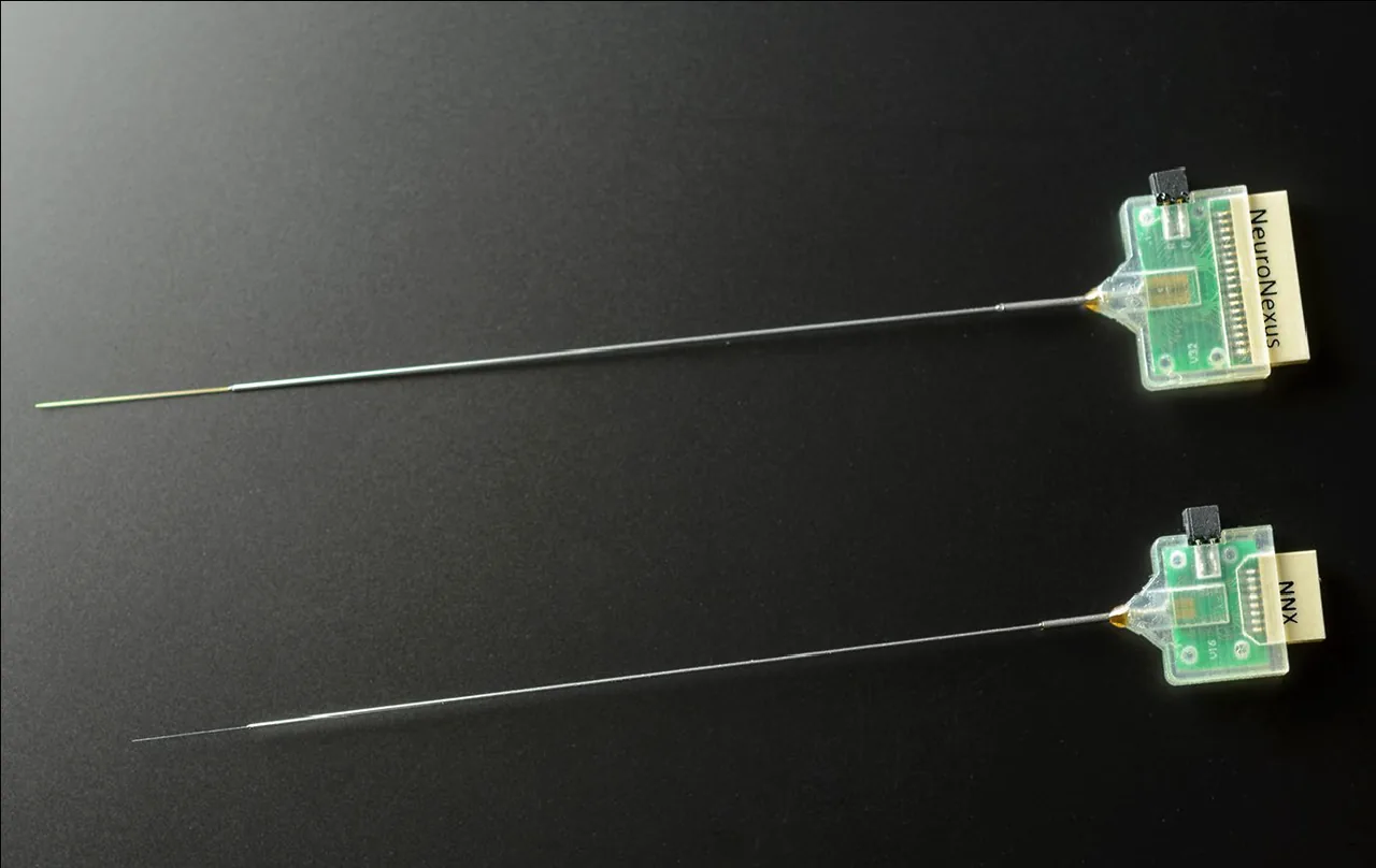
Laminar and polytrode layouts, or a custom array designed to your target.
Edge: Ten catalog designs at 16, 32 or 64 sites. Sites sit on the shank edge rather than the face, so less tissue is displaced relative to the recording surface — at the cost of sampling one side, which makes orientation at insertion part of the protocol.
Poly2 and Poly3: Multiple sites per depth for single-unit discrimination — three Poly2 designs at 50 µm pitch, one Poly3 at 25 µm.
Tetrode: Two catalog designs, 16 or 32 sites on a 15 mm shank with 121 µm² sites and a 300 µm cluster pitch.
Custom: Electrode geometry designed for an anatomical target the catalog does not reach.
Chronic Vector Array
A design enabling access to deep brain structures past 10 mm for chronic applications. Chronic builds configure to an implantable length of 30 to 55 mm — factor in implantation hardware such as clamps when configuring the probe.
Opto Vector Array
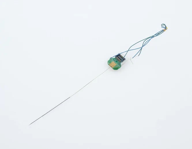
A flat optical fiber mounted alongside the array, so light arrives on the same trajectory as the electrodes rather than from a second implant with its own placement error. Carried on the OV16 and OV32 packages.
Eight flat fiber options: 50/62.5 µm at 0.22 NA (etched), 105/125 µm at 0.22 NA (standard), 200/220 and 200/225 µm at 0.22 and 0.39 NA, 400/425 µm at 0.39 NA, and 50/62.5, 105/125 and 200/220 µm at 0.66 NA.
One trajectory: The fiber adds cross-section down the whole tract, not only at the tip — plan the approach accordingly.
Plan for the artifact: Light reaches the electrodes as well as the tissue, so plan the analysis window around a photoelectric artifact at onset.
The Package Range
| Package | Channels | Connector | Built for |
|---|---|---|---|
| V16 · V32 · V64 | 16 · 32 · 64 | Omnetics 16 or 32-pin | The standard assembly, in a printed polymer case. |
| VC64 | 64 | Omnetics 32-pin ×2 | Chronic build. |
| VZ16 · VZ32 | 16 · 32 | Hirose 16/32-pin ×2 | Zif-Clip headstages. |
| VZC16 · VZC32 | 16 · 32 | Hirose 16/32-pin ×2 | Zif-Clip, in a printed polymer case. |
| OV16 · OV32 | 16 · 32 | Omnetics 16 or 32-pin | The Opto build, carrying the fiber. |
| FV128 | 128 | Omnetics | The Fusion-style double-sided array. Contact an application scientist to configure — not yet orderable online. |
From Array to Dataset
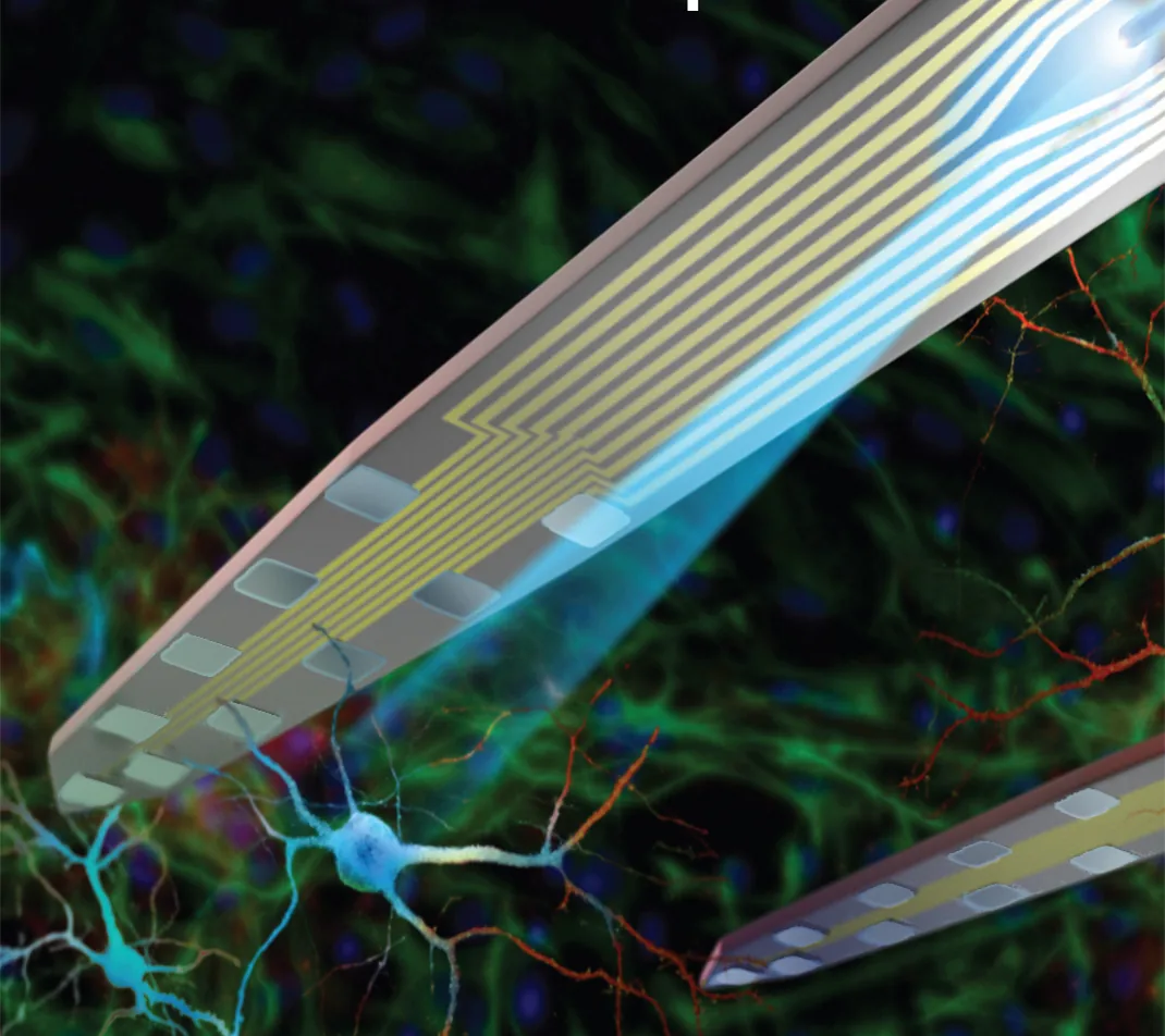
A probe design plus a package defines the orderable probe; the package connector then mates a headstage, and the headstage a DAQ. Every link below is one NeuroNexus supports directly.
Package
The package range runs on Omnetics or Hirose. Packages are not sold separately — the package is chosen with the probe.
Headstage
SmartLink 16, 32 and 64, and the X-Series X3R 32, X3R 64 and X6R 128.
Acquisition
SmartBox, and the XDAQ ALL-IN-ONE, CORE2 and ONE+ systems.
Software
Allego for acquisition, Videre for review, Radiens Compute for analysis.
Radiens Knows Your Vector Array
Every Vector Array ships with a characterized electrode model — impedance, geometry, and channel mapping — that Radiens reads automatically. During recording, Allego validates signal quality against the expected electrical characteristics of your specific array. This is Informed Acquisition: the software understands the probe.
Probe-Aware Channel Mapping
Radiens automatically loads the Vector Array's electrode geometry, shank layout, and site positions. No manual channel configuration.
Real-Time Signal Quality
Per-channel SNR, impedance, and noise floor monitored continuously during recording. Know the session is good before you remove the array.
Longitudinal Tracking
For chronic implants, Radiens tracks signal quality across sessions. Detect electrode drift or impedance changes before they compromise your dataset.
Everything a Vector Array Experiment Is Built From
Probes, packages, headstages, acquisition and software — the configured set.
Resources
Papers citing the use of Vector Arrays
Vector Arrays — FAQ
What is a Vector Array?
A short silicon electrode array mounted at the working end of a rigid stainless-steel support body. The support body resists buckling over a long trajectory, so the array reaches deep structures in large animals that a silicon shank alone could not — recording and stimulating only where the array is.
How deep can it reach?
Total length is 70 mm or 110 mm, with implantable lengths up to 110 mm. The silicon electrode itself is 10 mm; everything above it is structure. Chronic builds configure to an implantable 30 to 55 mm for targets past 10 mm.
Can a Vector Array be reused?
Yes. With proper care a single array is reusable across 50 or more experiments. The reinforced build adds structural reinforcement against breakage for improved longevity.
How do I choose a configuration?
Two independent choices: the site layout on the array — edge, Poly2, Poly3 or tetrode — and the build, which is standard, Fusion-style double-sided, reinforced, chronic or opto. A package then carries it to your headstage. Browse the catalog, or talk to an application scientist about the target.
Talk to a scientist about Vector Arrays
These are advanced configurations — tell us your target and preparation and we'll help you get it right.